
Model : WTAMP090012-50C-1(65W)
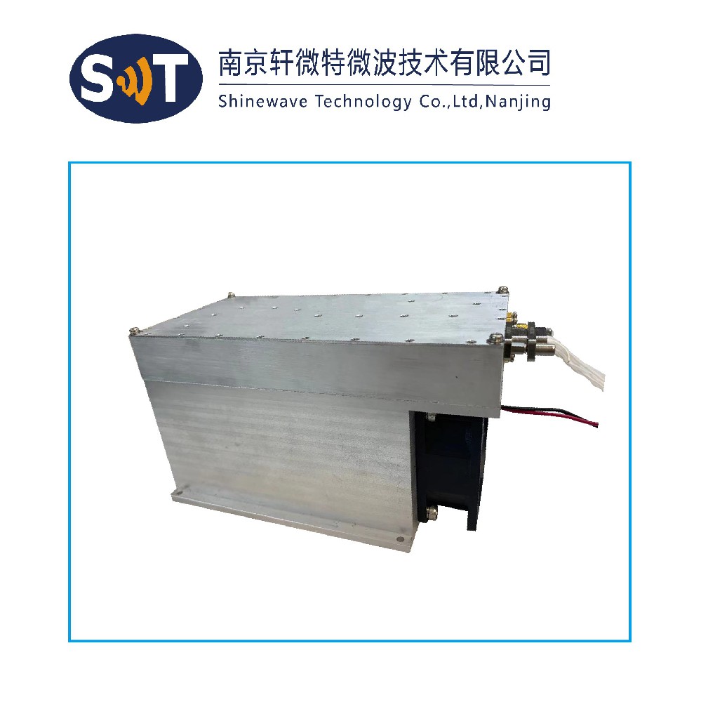
Solid State Power Amplifier
50 ohm input/output impedance
High reliability and ruggedness
SPECIFICATIONS @ +28VDC, 25°C, 50 Ω System
| Parameter | Symbol | Min | Typ | Max | Unit | ||||||||||||||||||||||||
| Operating Frequency | BW | 960 | MHz | ||||||||||||||||||||||||||
| Output Power cw | Pout | 48 | dbm | ||||||||||||||||||||||||||
| Gain | G | 50 | dB | ||||||||||||||||||||||||||
| Gain flatness | ΔG | ±0.75 | dB | ||||||||||||||||||||||||||
| Input Power for Nominal Output | Pin | --2 | dBm | ||||||||||||||||||||||||||
| Efficiency | 40 | 50 | % | ||||||||||||||||||||||||||
| Switching speed | 2 | us | |||||||||||||||||||||||||||
| Reflected Power for shutdown | 40 | dBm | |||||||||||||||||||||||||||
| Time Taken for Shutdown on Reflected Power ≥40dBm | 5 | µsec | |||||||||||||||||||||||||||
| Input VSWR | 1.5 | ||||||||||||||||||||||||||||
| Output VSWR | 1.8 | ||||||||||||||||||||||||||||
| Harmonic Signals | H | --20 | dBc | ||||||||||||||||||||||||||
| Spurious Signals | Spur | --60 | dBc | ||||||||||||||||||||||||||
| Operating Voltage | VDD | 28 | Volt | ||||||||||||||||||||||||||
| Current Consumption@65W | IDD | 5 | A | ||||||||||||||||||||||||||
MECHANICAL SPECIFICATIONS
| Parameter | Value | Units | Limits | ||||||||||||||||||||||||||
| Dimensions | 170×80×22 | Millimeters | Max | ||||||||||||||||||||||||||
| Weight | 2 | Kg | |||||||||||||||||||||||||||
| RF Connectors In/Out | SMA female | ||||||||||||||||||||||||||||
| DC interface Connector | J30J-15 | ||||||||||||||||||||||||||||
| Control Connector | J30J-15 | ||||||||||||||||||||||||||||
ENVIRONMENTAL CHARACTERISTICS(Design To Meet)
| Parameter | Symbol | Min | Typ | Max | Unit | ||||||||||||||||||||||||
| Operating Case Temperature | Tc | --40 | 85 | ℃ | |||||||||||||||||||||||||
| Relative humidity | 95 | % | |||||||||||||||||||||||||||
| Vibration /shock | MIL-STD-810F method 514.5 | ||||||||||||||||||||||||||||
DC INTERFACE CONNECTOR ( J30J-15)
| Pin | Description | Specifications | |||||||||||||||||||||||||||
| 1 | VDD | +28V±1V | |||||||||||||||||||||||||||
| 2 | VDD | +28V±1V | |||||||||||||||||||||||||||
| 3 | VDD | +28V±1V | |||||||||||||||||||||||||||
| 4 | VDD | +28V±1V | |||||||||||||||||||||||||||
| 5 | GND | Ground | |||||||||||||||||||||||||||
| 6 | GND | Ground | |||||||||||||||||||||||||||
| 7 | GND | Ground | |||||||||||||||||||||||||||
| 8 | GND | Ground | |||||||||||||||||||||||||||
| 9 | On/off | Amplifier Enable: TTL“High” (Logic 1) or Open Amplifier Disable: TTL“Low”(Logic 0) | |||||||||||||||||||||||||||
| 10 | Current monitor | Analog voltage relative to IDD@5A/V: IDD=0.14+5A*△V | |||||||||||||||||||||||||||
| 11 | Temp.sense | Analog voltage relative to module temperature @10mv/℃:V=0.5+10mv*△℃ | |||||||||||||||||||||||||||
| 12 | FWD PWR | Forward detected power (Analog:0-3.3Volt) | |||||||||||||||||||||||||||
| 13 | REV PWR | Reverse detected power (Analog:0-3.3Volt) | |||||||||||||||||||||||||||
| 14 | NC | NC | |||||||||||||||||||||||||||
| 15 | NC | NC | |||||||||||||||||||||||||||
OUTLINE DRAWING

ACCESSORIES
a. 02 right angle type RF connectors for MF-86 cable
b. 02 straight type RF connectors for MF-86 cable
c. 01 meter RF MF-86 cable
d. 04 right angle type RF connectors for Sucoform-141 cable
e. 04 straight type RF connectors for Sucoform-141 cable
f. 01 meter RF Sucoform-141 cable
g. 02 sets of electrical pigtail mating connectors
h. 01 heat sink
i. 02 sets of mounting screws (required for mounting amplifier with heat sink)
j. 02 sets of mounting screws (required for mounting amplifier without heat sink)